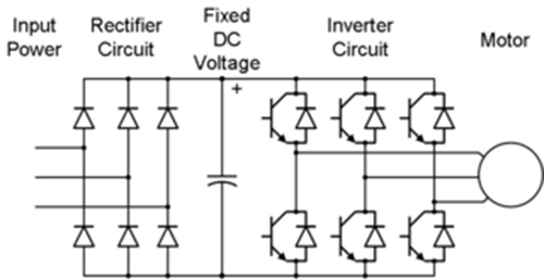
Single Phase Igbt Inverter Circuit Diagram
120° mode inverter – circuit diagram, operation and formula 12+ 3 phase igbt inverter circuit diagram Three phase inverter : circuit, working and its applications
SiC/IGBT 3 Phase Inverter Development Kit | Taraz Technologies
Sic/igbt 3 phase inverter development kit Inverter igbt power diagrams diode supply Igbt circuit module schematic fig4
Power circuit diagram of an igbt based single phase full-bridge
Inverter phase igbt electronicsInverter phase circuit schematic igbt Inverter igbt sic vfd spm taraz inverters dc leistungselektronik convertersVfd pwm igbt inverter rangkaian vsd skema induksi kecepatan trafo wiring frecuencia pengaturan mesin control vfds firing variador esquema circuits.
Circuit schematic of igbt modulePengaturan kecepatan motor induksi dengan inverter vfd atau vsd 3-phase pwm power inverter circuitInverter igbt.

Inverter phase circuit pwm bridge full power diagram three schematic switching voltage controlled
Three phase inverter schematicIgbt inverter pwm switching frequency 12+ 3 phase igbt inverter circuit diagramInverter circuit diagram 120 mode operation phase three bridge power formula figure shown below electrical.
12+ 3 phase igbt inverter circuit diagram .


120° Mode Inverter – Circuit Diagram, Operation and Formula

Circuit schematic of IGBT module | Download Scientific Diagram

Three Phase Inverter : Circuit, Working and Its Applications

12+ 3 Phase Igbt Inverter Circuit Diagram | Robhosking Diagram

12+ 3 Phase Igbt Inverter Circuit Diagram | Robhosking Diagram

SiC/IGBT 3 Phase Inverter Development Kit | Taraz Technologies

Three Phase Inverter Schematic | Download Scientific Diagram

3-Phase PWM Power Inverter Circuit

Pengaturan Kecepatan Motor Induksi Dengan Inverter VFD atau VSD